Wednesday, July 18, 2012

6 Wheeler Rover

Focus of project: Tight steering radius; utilizing the differential gear (for the first time)

When my best friend gave me all his old Lego parts (as he found himself and his siblings never using them) I found a lone differential gear lying in the box. Back then I did not even know how to use that part; but I did know for sure that was one of the most useful pieces in Technic. For those of you already familiar with differentials, the following (up until the rover video) won't be necessary to read though.

To the right we have two examples of Lego differential gears. The kind I have right now is the one on the right. The one on the left can only be used in bevel gear configuration. By themselves, the gears are nothing, just cylinders with tubes through them. They're made to contain 3 separate 12-teeth bevel gears on the inside, as shown below:


This is what a fully functional differential looks like. The function of this gear isn't too complex; it basically allows variance in the speed of both ends of the axle. Say the differential was motorized and the red and blue axles had wheels. If you were to slow one of the wheels down by friction, the differential would somehow transfer the energy lost by friction to the other wheel. This is especially useful for cars when they steer, since one wheel always makes a bigger circle than the other, and therefore their speeds must vary in order to turn smoothly. If you were to hold say, the blue end so that it doesn't move at all, the red end would double in speed.

To the right we have a real image of the lego parts needed to have a working differential. This particular differential gear has a gear fused on both ends to allow more variety of possible connections. The gear would be motorized by another gear connected to either of the fused gears. If the central bevel does not move, the ends of the axle will have the same speeds. If one of the vertically placed bevels slows down, the central one will speed up and so cause the opposite vertical bevel to speed up as well. This is what creates the phenomenon described along with the previous image.

Now to the actual project at hand. The 6 wheeler was intended to be an optional chassis for the next generation Lego Battlebots. Unfortunately, because my schoolwork got in the way so much, the game was not completed that year (I did make it a year later; stick around for the blog post). I only made a few embryonic prototypes of chassis and weapons, but eventually I realized the amount of work needed to complete it and the other simpler projects I had in mind would overrule any possibility of further developing the game. Ironically, I have a video but no pictures of this project. I hope you enjoy it:


As you saw this thing had double steering to meet up with the project focus. I thought, if this chassis will go against a tank chassis (the Battlebots standard), it better have decent maneuvering ability, especially because tanks can change direction in one place. I tried my best to make the return-to-center function work flawlessly, and I came pretty close by using some small rubber bands. Initially, the differential was motorized by two clutch gears (they stop spinning if too much torque is applied) but when I put a load on top of the chassis platform the rover didn't move. Therefore I replaced the clutch gears with regular, 24-teeth gears. Another issue I noticed was that during battle testing (again, with embryonic prototypes) the chassis platform easily came off the rover and made the idea of completing the game even more intimidating.

6 Wheeler Rover
PF Contents:

1 Battery Box
3 M Motors
1 Receiver
1 Remote

Sunday, July 15, 2012

Experimental PF Tank (Very Old)

Focus of project: Mere functionality


After digging through some ancient computer files I came across a few pictures of my first PF tank. It wasn't very impressive in relation to what Lego builders make nowadays but it was one of the funnest things in the world to operate. It's structure was pretty primitive but I do remember the first prototype breaking down altogether. This was way back when I only had about 10 gears in my inventory, another reason why this build wasn't so developed.


As you can see, there are two guns attached to the turret. This "gun permutation" was one of three, and two permutations had a sidearm as we see here. The main gun is the one with the ugly black magazine that protrudes straight up. It was, technically, "fully automatic", but its rate of fire was about 1 round every 2 seconds. Pictures of its mechanism can be seen below:

The line of gears is powered by nothing more than an M Motor. The reduction is so heavy that the "bar" (so I call it) has the strength to pull back a couple rubber bands (can't be seen here) and when the bar rotates 180 degrees the rubber bands release, firing the shot. The gravity-fed clip moves down once the firing pin is pulled back again, and the next rotation of 180 degrees fires the next shot. This mechanism is very primitive but it was technically my first automatic Lego gun.

You can see the bar much more clearly here. It's the black diagonal piece. Its pivot point is in its central pinhole (hence the 180 rotation every shot).

In all the pictures seen thus far, you may notice the turret movement mechanisms. The turning mechanism used an XL Motor with a heavily reduced gear ratio. It worked well but looking back I'd say a worm gear would've worked better. The vertical aiming was driven by a single linear actuator, since I only had one of them when I made this. It did the job, but the junction between both cylinders always bent when a heavy gun was mounted to the turret.

Here the 15 round magazine for the bar gun is opened at the top to reveal the ammo, which are 1-stud Technic bushings. Also, to the right of the picture, you'll see the sidearm of this gun permutation, which I basically took from YouTube username erahaar. Unfortunately, the video was taken down, possibly due to copyright issues with the background music. The gun basically was a really short piston that punched out the pins that are loaded on that protruding yellow clip. Its rate of fire was very high, but the range was very, very short. I considered it to be more of an automatic "flare" or "mortar" launcher.

Unfortunately, I wasn't considerate enough to take more pictures back then. However I do remember exactly what the other gun permutations were. For the first one I made, the main gun was a Bionicle sphere launcher (shown right) with an automatic mechanism. An XL Motor powered a piston that would blast the ball out of the grips in the cup, and a clip on top of it would feed the next ball in. The balls were pushed down by a rectangular piece loaded by a rubber band. The sidearm was a spring loaded missile (shown left) dubbed "Technic Competition Cannon". A motor pulled the lever on top and a compressed spring would launch the missile straight out. As you might imagine, such sidearm only had one shot. The second permutation was the one documented above. The third one was a revamped version of the bar gun. It was powered directly by an XL Motor (no gears) and the clip was not gravity fed. Also, the bullets actually looked like bullets. If I remember correctly, the magazines (there were 3, easily re-loadable by hand) each held 9 rounds. Like the sphere launcher weapon, the bullets were fed by a rectangular piece loaded by a rubber band. The rate of fire and range for the last permutation surpassed the other two, but there was no sidearm. Again, I apologize for not having any pictures of the other two weapons, but the most complex one was the one posted above.

On a side note, each receiver was marked with the corresponding amount of clear-orange studs to easily tell which channel it was on. There was also a set of LEDs on one side of the tank for nighttime scouting.

Thanks to YouTube username markdykstra36 for reminding me about this project (as I'm sure I wouldn't have posted it for a while) and for sharing his lego tank with me. His gun works much better than all the ones described above. Check his blog at droidfreakenterprises.blogspot.com.

Experimental PF Tank
PF Contents (including the motors required for all gun permutations to function):

2 Battery Boxes
2 XL Motors (1 for the chassis)
7 M Motors (5 for the chassis)
4 Receivers
2 Remotes
1 Speed Control Remote
1 Pair of LEDs
1 Linear Actuator

Wednesday, July 11, 2012

Lego Android Hand

Focus of project: Exploring the possibilities of the Lego universal joints


After some thought about how amazing the tiny universal joints are, I tried something new that involved a combination of them and the linear actuators. I literally spent no more than 20 minutes on this thing, and therefore it doesn't have full functionality. However, putting this up my jacket sleeve and using my hidden arm to control it brought quite a bit of attention at school.


You can clearly see the universal joints in the center up there, all 8 of them. The 4 fingers were driven by them but the thumb didn't need any. I used a small rubber band (seen in front of the lower motor) to insure the system operating the thumb wouldn't shift too far into the fist, because it did without it. The 4 main motors were connected into a square grid. Believe it or not, this thing could squeeze soda cans and bend them up pretty good.

Here's the video:

Lego Android Hand
PF Contents:

1 Battery Box
5 M Motors
3 Receivers
3 Remotes
5 Linear Actuators

Tuesday, July 10, 2012

Compact Lego RC Car

Focus of project: Compactness


So after quite a bit of experience with the PF system, I sought out to making the smallest possible RC car I could make, with the largest type of battery box (for it's the only kind I have). The result wasn't too bad, but I felt like the maneuvering wasn't as good as it could have been. Like all PF vehicles, it was very fun to operate, especially in a dark room because of the lights. Anyway, here are a few pics:

As you can see I used the link "bone" piece for the controller steering. This method is used by many Technic/Power Functions builders for their cars.


Here we have a close up of some of the steering parts. I used rubber bands meant for braces (unused ones, of course!) for the return-to-center mechanism. I used 2 yellow knob wheels (one is seen under the windshield) in bevel gear form to steer the front wheels. A very similar mechanism was used in the large RC car. The LEDs can also be seen behind the clear-blue plates. Most of the wires were able to make their way under the windshield.


Seeing as there was no other place, I stuck the receiver in the back. It wasn't protruding too much, as you will see in the side view, but the asymmetry bugged me. However, there just was no way to attach the receiver symmetrically (without it protruding really far), since it only has 2 pinholes in the front. You can also barely see a bevel gear on the bottom; I wasn't able to fit a differential in there. It didn't really matter for a car of this size.


From the side view we see how few Technic beams (the long yellow parts) I used throughout the build. You might even be able to tell how the battery box was removed; the windshield was lifted to permit the battery box to be folded up. The 3-stud yellow beams would be removed from the sides to allow the box to just slide off the rails it was loaded on. Making the battery box easily removable can be key to any PF creation you plan on playing with for a while. Even though that wasn't the case for this creation, it was a necessary aspect to fulfill for the project's focus.

Ah yes. I finally have a video to present along with all the photos. Enjoy!


As you saw the weight of the battery box in the back caused this thing to make a wheelie upon rapid acceleration.

Compact Lego RC Car
PF Contents:

1 Battery Box
2 M Motors
1 Receiver
1 Remote
1 Pair of LEDs

Lego Battlebots: First Generation (built in late 2009)

Focus of project: Fun


So after making a few terrible (but fun) RC cars, I had this idea, this wonderful idea. The idea stemmed from my childhood passion of inventing games; be it on a board, with cards, or on a screen. Eventually this passion was replaced with engineering, but it will never be erased from my mind. The idea was a new type of Lego game - one that would be packed with excitement, strategy, and sheer awesomeness. Unfortunately, the end result didn't fully reach these expectations, but it indeed came pretty close. I present to you the first generation Lego Battlebots:


Whoa, what? No, not robots that destroy each other. Rather, each player had to destroy a single part - called the "flag" - that lied on the edge of the enemy's platform. The red piece on the left bot (above) was the red bot's flag and on the right we see the blue bot with its flag. If you notice, both bots have 2 vacant motors on their platforms. These motors controlled the weapons, which the players got to choose themselves. I built an array of melee weapons, most of which had duplicates in case both players wanted the same weapon. [I attempted to make an automatic gun out of the Bionicle ball launchers; it worked but it shook the bot too much and eventually the gun would fall off.] To win, the players had to use their two weapons to try and dismount the enemy flag.

The weapons were all built to attach instantly to the motor. Because I didn't have enough M Motors at the time, one of the weapon motors was an XL, which sometimes gave too much power to some weapons:


I would have liked to have both weapons run on M Motors, but I had only enough for one for each bot:


The parts built around the motors allowed them to attach to the platform, wherever the player wished. Some weapons attached to be in parallel with the motor, and some perpendicular. Here we see a bot with its motors and receivers mounted on the brick platform. These 4 items could be moved wherever it would be convenient for weapon placement. You may think, "Can't the enemy's weapons get tangled in those wires?" Well, unfortunately, the answer would be yes. The wires were typically tucked into the middle of the platform (where to parts lied) to avoid this issue, but  this problem was completely eradicated in the second generation Battlebots.

Battlebot Chassis:

Pros:
High speed, easy maneuvering, color coded motor placements.

Cons:
Wires everywhere, delicate in the areas made with brick parts, XL Motor was at a higher altitude than the M Motor, too much platform space taken up by the motors and receivers; XL Motor mount came off after a couple battles.

Here we have the bot controllers. As you can see, the small brick parts all over the controller were all utilized for color coding. The two levers controlled the tracks, and the two dials controlled the weapons.

Pros: Color coding, compactness.

Cons: Sometimes players would confuse the controls, rotating a dial too much could cause a weapon to shake itself off the bot (i.e. Hammer), could be split among two people to have a "driver" and a "gunner".

All the weapon variants had different mechanisms. Most of them would function the same way regardless of which direction the motor spun. I have some old photos of them below; I still didn't have a legitimate video camera at the time so I hope I deliver them all well enough.

The Saw.
This was by far one of the best weapons in the game. I designed it to be placed either vertically or horizontally, but quickly learned that putting it vertically is much, much less useful than horizontally.

Pros:
Effectiveness, reached out a good distance with its length.

Cons:
Kill radius was too large, blades could be pulled out easily.

Amount in arsenal: 2

The Hammer.
This was the most popular weapon. When activated, the two blades would constantly move up and down, and went really rough on the enemy flag. It made the game interesting when it took multiple hits to fully take out the flag. Sometimes the flag would be between the two blades as they fell right over it, not making a kill. I came up with its mechanism by accident.

Pros:
Effectiveness, could be used as a defense arm to hold away the enemy

Cons: Could get pretty shaky at high speed, mechanism would sometimes dismantle itself.

Amount in arsenal: 2

The Sweeper.
This weapon had a raking mechanism. essentially, it was a piston but it was held by the other end, so that the "piston head" would move in a circular motion instead of a vertical cycle. Move the motor one way, it would pull the flag in; move it the other, it would push the flag out.

Pros: Effectiveness, two different motion types, good range.

Cons: Got shaky at high speeds, the blade section could be pulled out easily.

Amount in arsenal: 2

The Pincer.
This was the most complicated one in the arsenal. Whenever the internal piston went backward, the jaws closed, and when it moved forward, a rubber band would open them again. The piston cycled constantly to create a bug mandible effect.

Pros: None really.

Cons: Front had to be supported by some extra bricks underneath (or else it would hang), the grey knob wheel (shown between the blades) slid out after many cycles (causing the piston to have no purpose), could only be connected to the M Motor - with bricks laid under it - to raise to the right altitude (even the XL was too low).

Amount in arsenal: 1


The Flail.
My apologies, but this is the best picture I have of it. Yes, the motor had to be removed from its cage to put it on the vertical platform. This weapon was probably the strongest of them all, but caused the most problems. The light grey axle you see on the end of the chain would go into the orange connection in the motor. You can imagine the rest.

Pros:
Strength, kill radius

Cons:
Axle easily popped off the motor, could easily get tangled in the bot's own wires, sometimes would start rotating but would then get stick against the vertical motor platform (because the speed remote cannot immediately start immediately at a high speed), got very shaky most of the time, motor sometimes fell off all together (yeah, awesome, but full of problems).

Amount in arsenal: 1

The Drum Roller.
This was the last weapon to be added to the game. It worked quite peacefully and never experienced any issues. The mechanism was quite simple yet very useful for its purpose. When activated, the red rubber band acted as a belt to spin the grey rods, creating a rotating mess of sticks. The rods were oriented so that when rotating they would look like a sine wave.

Pros: Not overpowered but not useless, the only weapon to be able to attach to a motor and removed without any pegs ever "sticking" to the motor, compactness.

Cons: Very short range.

Amount in arsenal: 2

So that's the first generation Lego Battlebots game. As you read, it was full of issues, but even with them in the mix, the game was a TON of fun. I brought the whole system to school and lines started forming (I should have charged a quarter for each tryout!) to play the game. Sure, there were many moments where I intervened for a brief repair job, but such moments were key to learning about how to build the second (and latest) generation, which I built two and a half years later. I will make a post about it, but this is (generally) a chronological blog, and I made many creations worth blogging about between the two versions. Yes, I invented this exact game, but inspiration came from the official Battlebots series.

Lego Battlebots: First Generation
PF Contents:

2 Battery Boxes
2 XL Motors
6 M Motors
4 Receivers
2 Remotes
2 Speed Control Remotes

Monday, July 9, 2012

Large Lego RC Car (built sometime around 2008/9)

Focus of project: Design, Color Scheme, and Fun


So I guess I'll start with an easy one. After several attempts at making several RC cars, I finally got to make one that I felt was worth photographing. Now I didn't have any real video cameras at the time (this was about 4 years ago; now I have a good one), so I only have pictures for this creation. It was a rather slow moving, but powerful vehicle, and was one of the first of my machines to be built with a color scheme.


This build wasn't very professionally made, in terms of internal mechanisms, because I didn't have as many sophisticated parts at the time. As you can see below, both rear wheels were powered by direct drive and no differential axle between them. The car didn't have suspension, either. My only goal with this build was to make a car that works flawlessly with the functions that it had (all my previous cars always had some sort of mechanical issue), and I achieved this goal here for the first time.


The return-to-center mechanism wasn't very well made either:


Essentially, all I did was perform several tests of trial and error until I had the right rubber band power that the turning motor could overcome, yet the power was just enough to defy the motor's torque and return the two front wheels to facing forward again. This would happen the moment you let go of the turning switch on the remote, which would cut off power to the turning motor. This particular steering system worked quite well.

The main reason for this build was to get some experience in making a good-looking, fun car to drive around. I learned that those red parts in the top front were made to perfectly house the PF LEDs, which made it look beautiful in the dark (my apologies for not taking such photos).

I have made instructions for this build several years ago by taking photos of every step, and I feel some of those photos would be nice to show to get a good glimpse of what's under the hood:

The battery could be removed and refilled easily; you just had to lift the driver's window, disconnect the receivers, and slide the battery box out.

Large Lego RC Car
PF Contents:

1 Battery Box
2 XL Motors
1 M Motor
2 Receivers
2 Remotes
1 Pair of LEDs


The Power Functions (PF) System

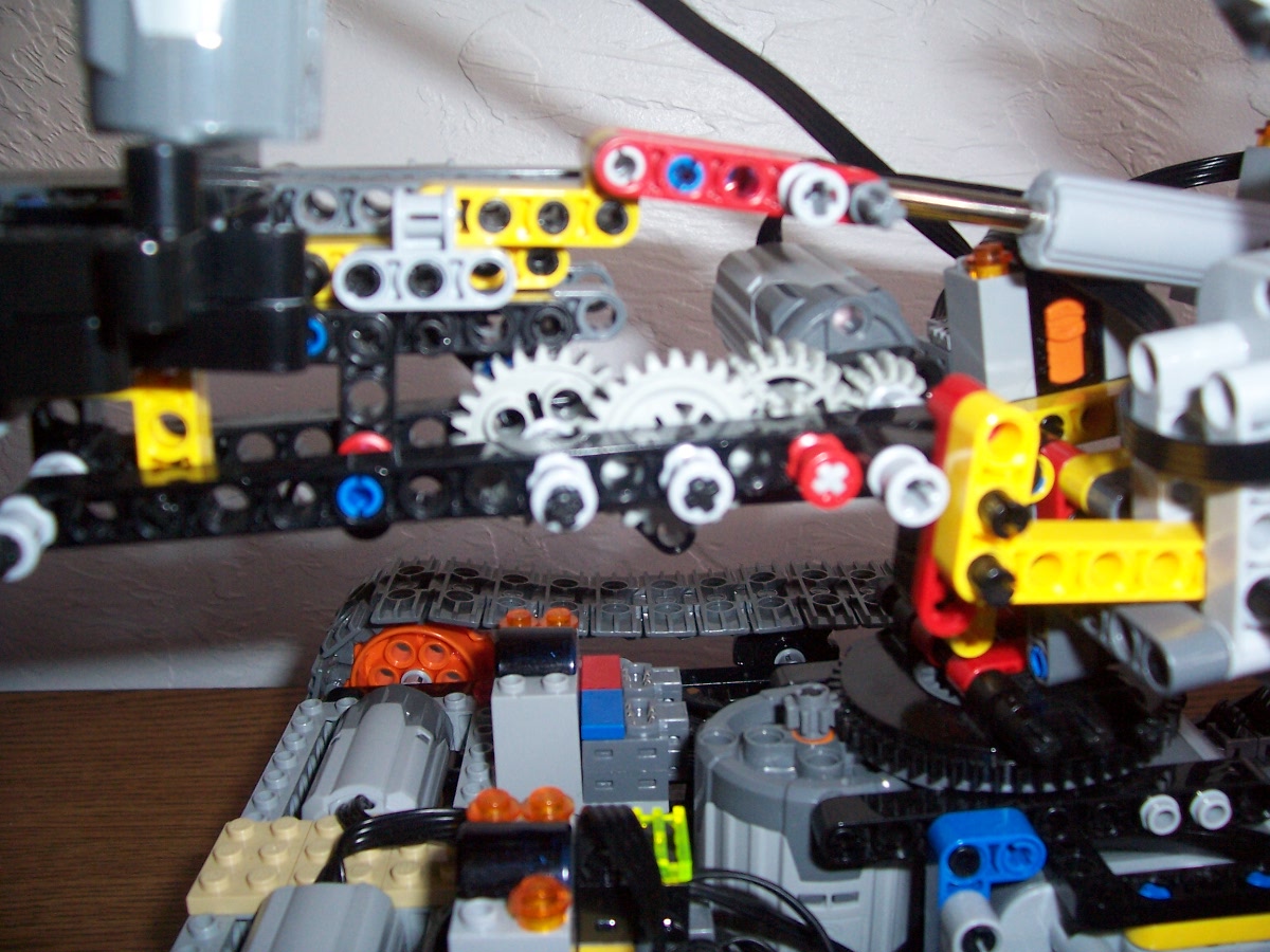
Ah yes. Yet another overview by another internet geek about Power Functions. If you feel you know the whole system already, just skip over this post and check out the Large Lego RC Car. Otherwise, read on to understand how compelling and useful all the PF parts really are. Lego truly gave its Technic fans a gift when they came out with all the parts I'm about to lay out for you. [Side note: Dimensions are in "studs", which is the length of a single Lego connection space]

The PF system consists of batteries, motors, and remote control equipment designed to bring your lego machines to life. They can connect to almost any Lego Technic elements, such as gears, wheels, and levers. Technic is a line of Legos that doesn't look like your average Lego bricks; instead these parts interlock in the form of axles and pinholes. Almost all Power Functions parts have such connections around them as well. You will also notice that the PF system has the color scheme of dark grey, light grey, and orange throughout all its elements.

Let's start with the power sources.

To the right we see the standard, 9 Volt battery box. It houses 6 AA batteries, 3 on each side, and has an orange switch at the top. Sliding the switch to the center position turns it off. Sliding it to the left will turn it on, and sliding it to the right will reverse the circuit. A green LED next to the switch turns on to indicate proper functionality. The grey connection at the top is where other functional elements can be "stacked". For example, you can stack 4 motors on the battery box. When you turn it on, all 4 of them rotate in the same direction. Likewise, receivers, the elements that take in signals from a remote, can also be stacked to allow for more functions coming from a single battery box.

AA Battery Box:
Dimensions: 4x8x11. Amount in my inventory: 5


To the left, we have the recently produced AAA battery box. This compact power source delivers the same amount of voltage but less amperage than the standard battery box. Also, it only has "brick" connections, so parts must be added to connect this to a Technic platform. The orange switch indicates the circuit's direction, and the green button turns it on.

AAA Battery Box:
Dimensions: 4x8x4. Amount in my inventory: 0


Now we see the PF Rechargeable Battery Box. Packed with top-of-the-line features, this thing is famously overpriced at a whopping $50. It is small, much lighter than the other batteries, has a "speed control" dial, and contains lithium polymer cells. The charger is purchased separately, for half the price of the battery. It looks just like the AAA box, but has a charging inlet and a dial instead of a switch, which controls how much power it puts out. Turning the dial in the opposite direction slows down or reverses the circuit. The green button turns the battery on and off, and it starts the battery at the same speed setting that it had before it was turned off. There are 7 speeds, plus 7 more in the opposite direction.

Rechargeable Battery Box:
Dimensions: 4x8x4. Amount in my inventory: 0

Alas, the all powerful XL Motor. This is the largest of all Power Functions motors. It packs quite a bit of torque to any Lego machine, and is commonly used for heavy duty purposes.

XL Motor:
Dimensions: 5x5x6. Amount in my inventory: 3


Now we study the all too common M Motor. This is typically featured in sets that have a single motorized function, such as a dump truck with a functioning bucket. Therefore, it is no surprise that this is the motor used for almost all custom Power Functions builds. It has a little over half the torque of the XL Motor. It also has a 2x6 brick frame on the bottom.

M Motor:
Dimensions: 3x3x6. Amount in my inventory: 12

Behold, the BRAND NEW Lego L Motor. This motor is so new it's not even available for purchase yet. It will be featured for the first time in a remote control rock crawler set, which will be the first RC car with suspension that lego will have ever released.
This motor supposedly has more torque than the M Motor but less than the XL

L Motor:
Dimensions: 3x4x7. Amount in my inventory: 0


Guess what? Another brand new motor. This one's called the Servo Motor and is designed for steering systems in cars, and will likewise also be featured in the new rock crawler. It has its own return-to-center ability that defies heavy torque resistance. However, it does not rotate endlessly. It can only do 90 degrees CW and 90 degrees CCW. When a normal remote activates it, the motor takes the full 90 degree angle. When the button is released, the motor forces itself back to zero degrees. An amazing feature about this motor is that when used with the speed control remote, which ever "speed" you rotate the dial will match the angle of the servo motor. In other words, the remote has 7 motor speeds in both directions, but the Servo Motor has 7 angles in both directions, plus the central position. That makes 15 positions, each 12 degrees apart from one another. Each "click" on the speed dial causes the Servo to rotate 12 degrees. The dial on the Rechargeable Battery Box acts the same way. Also, there is a second axle connection behind the orange one shown in the image.

Servo Motor:
Dimensions: 3x5x7. Amount in my inventory: 0

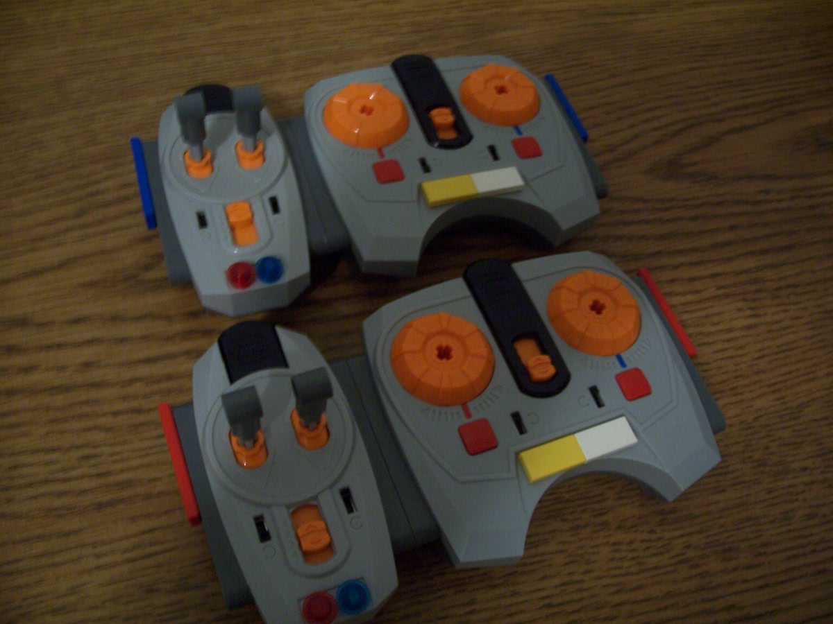
Say hello to the PF Infrared Remote. This is the handset most commonly used to control PF creations. The levers are not pressure sensitive and so cause motors (and lights) to operate at full power when one of the levers are pushed up or down. The black switches on the sides change the direction of the corresponding motor's circuit, to adjust to the user's convenience. The central orange selector switch has 4 positions, each corresponding to the 4 infrared channels the remote can operate with. If the receiver unit is on the same channel, the remote will control that receiver. Also, the red and blue tick marks above each lever correspond to the red and blue tick marks on the receiver (because both the remote and receiver can control two motors). The remote houses 3 AAA batteries above a 4x8 brick platform.

IR Remote Control:
Dimensions: 6x4x10.5. Amount in my inventory: 4

To right lies the Infrared Speed Remote Control. Instead of vertically moving levers, it uses rotating dials. The black switches and the orange selector switch perform the same functions as the normal remote. The dials can be rotated CW or CCW, likewise giving the motor speeds in both directions. Each time you feel a "click" when rotating the dials, the motor changes its speed by 1 setting. To stop a motor all together, simply push the red button under its control dial. Unfortunately, there comes a point where dialing too fast will cause little to no response from the receiver. This remote is best operated by rotating the dials slowly. Like the normal remote, it houses 3 AAAs.

IR Speed Remote Control:
Dimensions: 4x12x11. Amount in my inventory: 2

Here we have the almighty Infrared Receiver. It has the ability to sense signals from both types of remotes, at a limited range, supposedly 10 meters. After a few experiences I found that the range decreases dramatically in the sun. The selector switch differentiates between the 4 IR channels, and any remote on the same channel controls whatever is attached to that receiver. Even if there is no element attached, a small green LED (next to the orange switch) flickers when a signal is sent to the receiver. Otherwise, this LED remains bright at all times. The receiver only has 2 Technic pinholes but a 4x4 brick platform underneath. [I've tried attaching receivers to other receivers. Nothing happens when you press a control.] An updated version of this thing called the Receiver V2 will be featured in the new rock crawler set. My hope for it was to have more channels, but it simply has better internal parts and allows for 2 L Motors to both run at full power even when one stalls. It looks the same as this one, except the "V2" printed between the pinholes.

IR Receiver:
Dimensions: 4x5x4. Amount in my inventory: 6

What we see now is the "Power Functions Light". I prefer LEDs or Lights. Although not very useful for mechanical purposes, these can really add to the swag of your creation, especially if it's a car. Statistically, 100 of these units can be stacked on a battery box before they start to dim.

Power Functions Light:
Dimensions (for each LED): 0.5x1.5x1.5. Amount in my inventory: 1


Now we go for some mechanical parts. To the left I present the Linear Actuator, a PF part that is not officially sold separately. It converts rotary motion into linear motion with a screw mechanism. It can extend 5 studs from its contracted position. There are a few types of parts that were made to specifically fit around the orange connection, to act as "adapters" for motors or gears. The first versions of these endured some friction; when the Lego Excavator set came out and complaints were reported about the nonfunctional arm, this part was remade to require less torque to extend the cylinder.

Linear Actuator:
Dimensions (while contracted): 2x2.5x11. Amount in my inventory: 6


Last, but certainly not least, we have the Mini Linear Actuator. It does not differ much from the normal actuator in terms of functionality, but it extends only 3 studs from its contacted position. Also, it has a permanent "adapter" on the back of it, the kind which cannot attach to motors directly.

Mini Linear Actuator:
Dimensions (while contracted): 1x3x7.5. Amount in my inventory: 4

Whoops, almost forgot. In case you decide to make a device that requires no wireless connectivity, the handy dandy Control Switch is the way to go. It has the exact same functions as half of an IR Remote Control, but with a cable. The lever does not spring back to the middle, however, when let go. You can there for leave a motor running indefinitely and easily shut it off (this switch is much easier to shift than the sliding switch on the battery box).

Control Switch:
Dimensions: 2x3.5x5. Amount in my inventory: 2

Well there you have it. That's the Lego Power Functions system. Now that you have seen it all (except for the extension chords; I hope you understand how those would work), imagine the possible machines that can be made with these parts. Imagine all the vehicles, robots, and even games that one can build - just by using these small parts!

Sunday, July 8, 2012

Welcome to my blog.

Greetings to all who come across this site. I intend this blog to be for Lego fans and non-fans alike, for my sole purpose of leading this blog is to show the world what sorts of innovations can come from this brilliant toy system. I say that childishly because at heart most believe Legos are mere toys, but by the time you get through all the creations I've made so far, you might begin to reconsider the potential of these plastic bricks. My projects mainly focus on Lego Power Functions, a recently developed series of electrical parts consisting of motors, batteries, and remote control equipment. Power Functions can be implemented into any mechanical Lego creation to breath life into it. Luckily, Lego has all sorts of gears, wheels, and levers to combine into any machine you want, and Power Functions put it all into full glory. My brother and I have acquired a vast inventory of such parts and I have come to the point where I must document all my projects textually. On occasion, I will post details of creations not containing Power Functions, but they will also reveal yet more of the amazing possibilities of lego parts.